Zephyr RTOS Bootloader
Introduction
Zephyr RTOS Bootloader
In this Codelab, you will first learn the basic principles of integrating a bootloader application in Zephyr RTOS. You will then learn how to download and install new applications securely.
What you’ll build
- You will integrate the MCUboot bootloader application into your Zephyr RTOS application.
- You will then implement a download mechanism for storing a new application and installing it.
What you’ll learn
- You will learn the basic principles of bootloaders and their implications for Zephyr RTOS program images.
- You will also understand how the boot sequence is modified to start an application with a bootloader.
What you’ll need
- Zephyr Development Environment for developing and debugging your program in C++.
- The Memory Profiling and Optimization codelab is a prerequisite for this codelab.
The Bootloader Principle
A bootloader is a type of application that allows system or application software to be updated without the use of specialised hardware, such as a JTAG programmer (or other programmers for different MCUs). The bootloader manages and installs system or application images. In specific cases, it may also download them. Throughout the rest of this document, we will often refer to the system or application image as ‘firmware’. We will also refer to the process of downloading and installing new firmware as ‘DFU’.
DFUs/bootloaders can communicate using a variety of protocols to download firmware and save it to the non-volatile memory of the embedded system. These protocols can be UART, Ethernet, USB or a wireless protocol for systems with wireless connectivity. As well as downloading new firmware, DFUs/Bootloaders are responsible for verifying its integrity and authenticity.
Usually, systems with bootloaders have at least two firmware images coexisting on the non volatile memory of the MCU. They must also include code for branching installation of a new firmware image.
It is very common that the need for a bootloader mechanism is overlooked when conceiving embedded system software, because the bootloader is not the end product. However, the bootloader is an essential component of an embedded system. It allows to launch a system with software that only fulfills a subset of the final requirements and to add features to the product once it has already been launched to the market. And, even more importantly, it also allows the developers to fix bugs that are discovered over the lifetime of the product and to deploy corrections.
Writing a bootloader application requires an understanding of how a program image is built and how the MCU uses this memory. In this codelab, we will develop a simple bootloader and explain all components required for its development.
The Zephyr RTOS Memory Model
From the lecture notes, recall that the Zephyr RTOS/MCUboot memory model is as depicted in the figure below:
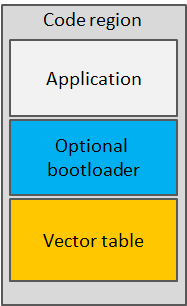
It is important to note that this is not the only applicable model, and that other memory models are also possible (for instance, where the bootloader is not located before the application in ROM). However, on Cortex-M MCUs, the MCU expects the application to start by reading the SP and PC at the start of the ROM. Therefore, locating the immutable bootloader at the start of the ROM is not really an option.
Boot sequences
In general, a boot sequence can comprise several stages before reaching the application. These stages include several bootloader stages and the application itself. Except for the immutable bootloader, all stages can evolve over time and be upgraded to add new features and correct bugs. Upgrades are possible for boot sequences with two or more stages: any active stage can replace the next stage in the sequence, meaning that when the system restarts, the updated components (including the updated application) will be executed. The very first stage is usually immutable because it takes control on startup, so a faulty upgrade could be very difficult to recover from.
Usually, for protecting against faults in a newly updated component, multiple versions of each stage are stored in the non volatile memory. Each stage is responsible for detecting faults in the next stage and for rolling back if a fault is discovered.
Our simple implementation
In this codelab, we will implement different options for a simple two-stage boot sequence: a bootloader that won’t be upgraded and an application that will be upgraded. Most boot sequences usually comprise at least three stages: a root bootloader or boot selector that is not upgraded, and two upgradable stages (bootloader and application) with multiple versions stored on the device. In our implementation, the bootloader acts as both a boot selector and a bootloader, capable of installing new images.
Compile and Install the MCUboot Bootloader Application
Integrating multiple applications using sysbuild
The integration of the MCUboot bootloader with a Zephyr RTOS
application is often achieved using the Zephyr RTOS sysbuild
higher-level build system. This system enables multiple builds to be
combined and multiple applications to be flashed or debugged simultaneously.
For the sake of simplicity, we will build and flash the MCUboot
bootloader and the BikeComputer program as two separate applications.
Import MCUboot into Your Workspace
The following steps explain how to import MCUboot into your Zephyr RTOS workspace:
- Add the following to your
west.ymlfile:manifest-repo/west.yml... import: path-prefix: deps file: west.yml # not strictly needed since it is the value by default name-allowlist: ... - mcuboot - mbedtls - tf-psa-crypto - zcbor ... - Run
west update. - Check that the MCUboot bootloader is available in the “deps/bootloader” folder.
Build the MCUboot Application
The following steps are required to build and flash the Zephyr RTOS MCUboot bootloader application:
-
Create a
prj_bootloader.conffile in the root directory of your workspace. This configuration file is used to build the MCUboot bootloader application. Some changes are required for the application to work properly:prj_bootloader.conf# Set the default logging to DEBUG level CONFIG_LOG_DEFAULT_LEVEL=4 # Allow malloc() to be used in the application CONFIG_COMMON_LIBC_MALLOC_ARENA_SIZE=1024 -
Build the MCUboot bootloader application as a standard Zephyr RTOS application by running
You will see a warning that says, “Using default MCUboot signing key file, this file is for debug use only and is not secure!”. This is not an issue at this point. You can also ignore the other warnings.west build deps/bootloader/mcuboot/boot/zephyr --pristine --extra-conf ../../../../../prj_bootloader.conf -d build_bootloader -
Flash the application with
west flash -d build_bootloader. The following output should appear on a serial monitor:Serial Terminal*** Booting MCUboot v2.4.0-rc1-3-gee39e2d694bd *** *** Using Zephyr OS build v4.4.0 *** I: Starting bootloader I: Image index: 0, Swap type: none I: Image index: 0, Swap type: none I: Primary image: magic=unset, swap_type=0x1, copy_done=0x3, image_ok=0x3 I: Secondary image: magic=unset, swap_type=0x1, copy_done=0x3, image_ok=0x3 I: Boot source: none I: Image index: 0, Swap type: none W: Failed reading image headers; Image=0 E: Unable to find bootable image
The bootloader is running correctly at this point, but, as expected, it cannot find a bootable image.
Modify Your bike_computer Application To Integrate a Bootloader
In order to run the bike_computer application from the bootloader application, you must
add some configuration parameters to the bike_computer program as follows:
-
Create a
prj_dfu.conffile in the root directory of thebike_computerapplication with the following content:bike_computer/prj_dfu.confThis allows the image to be chain-loaded by MCUboot. It also instructs# Enable Zephyr application to be booted by MCUboot CONFIG_BOOTLOADER_MCUBOOT=y # Configure application signing CONFIG_MCUBOOT_SIGNATURE_KEY_FILE="deps/bootloader/mcuboot/root-rsa-2048.pem" CONFIG_MCUBOOT_IMGTOOL_SIGN_VERSION="1.0.0+0"west buildto sign the image with the default MCUboot key file. This key file will be modified later. Finally, this adds versioning for signing the image. -
Build the application using command:
just build bike_computer log_app+debug+gpio+display+sensor+phase_c yes prj_dfu.conf. This command will build thebike_computerprogram using the specified configurations and theprj_dfu.conffile.
After flashing the bike_computer, the bootloader should jump to the first image slot at startup
and the bike_computer program should start up normally.
Signing the bike_computer Program and Provide the Key to the Bootloader application
An important aspect of the image update process is that images uploaded to the device must be signed. If this is not the case, and if the MCUboot is configured to verify the image, the MCUboot application will reject the candidate images because it needs to verify their authenticity. For this reason, the bootloader must embed the key used to sign the application.
In the previous steps, the MCUboot application was instructed to use the
default key and the bike_computer program was signed with this key.
However, each program should use its own generated key.
The MCUboot project includes the bootloader/mcuboot/scripts/imgutil.py
script. This script allows you to, among other things, generate a pair of keys,
extract the public key, and generate the .c file containing the public key
that will be integrated into the bootloader program. Therefore, it is necessary to:
-
Install the dependencies listed in
deps/bootloader/mcuboot/scripts/
requirements.txt
using the commandpip install -r requirements.txt. -
Create a directory named
keysin the root workspace directory and generate a key pair usingpython deps/bootloader/mcuboot/scripts/imgtool.py keygen -k keys/private_key_rsa-2048.pem -t rsa-2048. Theprivate_key_rsa-2048.pemfile contains the key pair that will be used to sign the application.
Once the key has been generated, you must instruct the MCUboot application to embed it
and sign the bike_computer program with it. This can be done as follows:
- Modify the
prj_bootloader.confconfiguration file by adding:prj_bootloader.confCONFIG_BOOT_SIGNATURE_KEY_FILE="full path to private_key_rsa-2048.pem" -
Build the MCUboot application and flash it. The
bike_computerprogram installed in the primary slot should now be detected as invalid:Serial Terminal*** Booting MCUboot v2.4-rc1-3-gee39e2d694bd *** *** Using Zephyr OS build v4.4.0 *** I: Starting bootloader I: Image index: 0, Swap type: none I: Image index: 0, Swap type: none I: Primary image: magic=unset, swap_type=0x1, copy_done=0x3, image_ok=0x3 I: Secondary image: magic=unset, swap_type=0x1, copy_done=0x3, image_ok=0x3 I: Boot source: none I: Image index: 0, Swap type: none I: Image index: 0, Swap type: none I: Image index: 0, Swap type: none I: Image index: 0, Swap type: none E: Image in the primary slot is not valid! E: Unable to find bootable image -
Modify the
prj_dfu.confconfiguration file by changing the path to the key file. Build and flash the application. It should now be recognized as valid again and it should start up normally.
The MCUboot and bike_computer program are now ready to receive updates.
The next sections will cover two different methods of updating a Zephyr RTOS
program.
Update the BikeComputer Program using Serial Recovery
One way to update a Zephyr RTOS program is to download the software update from the bootloader itself, as shown in the diagram below:
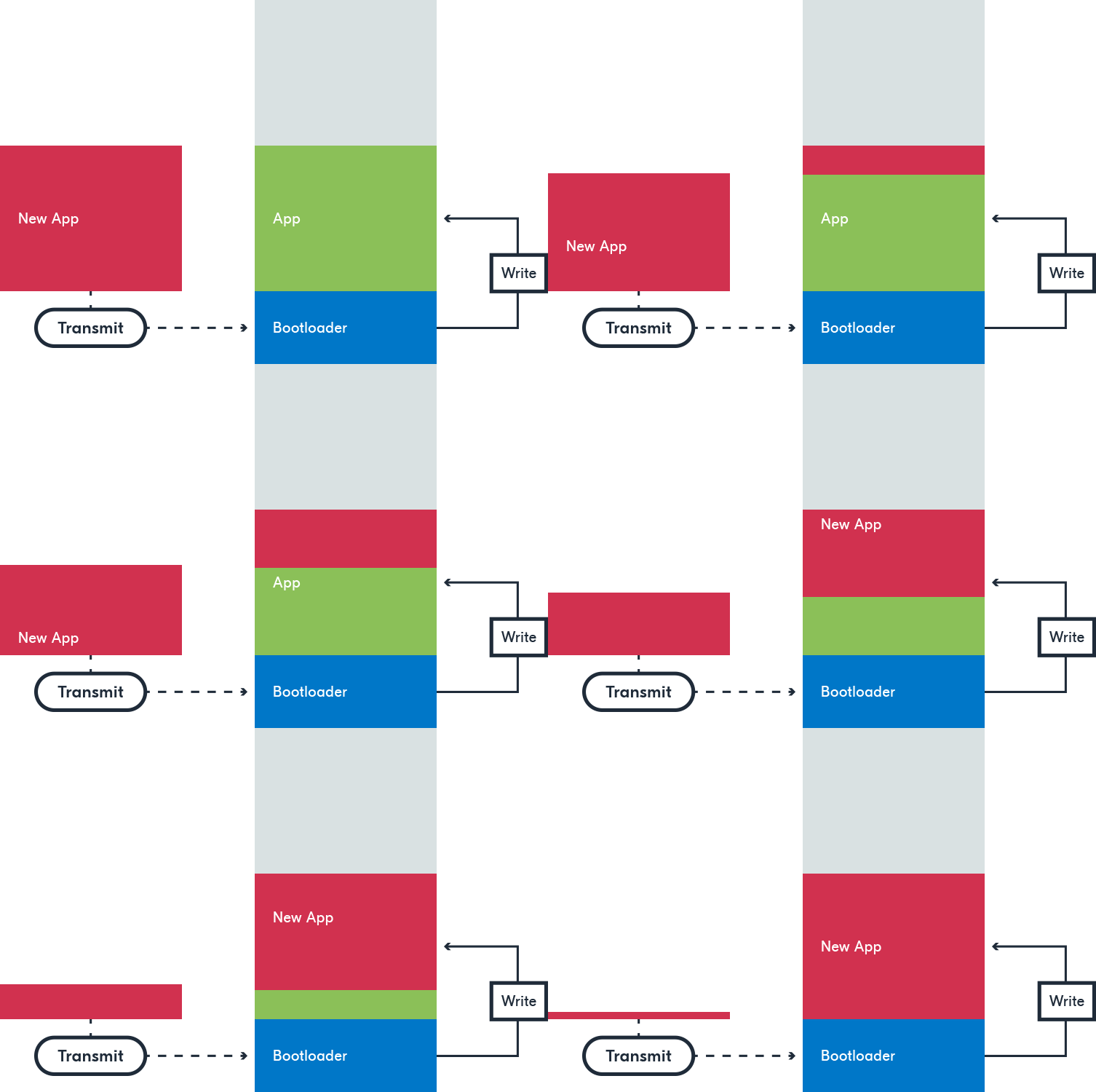
To implement this solution, the download will be executed from the bootloader application via UART. The setup is shown below:
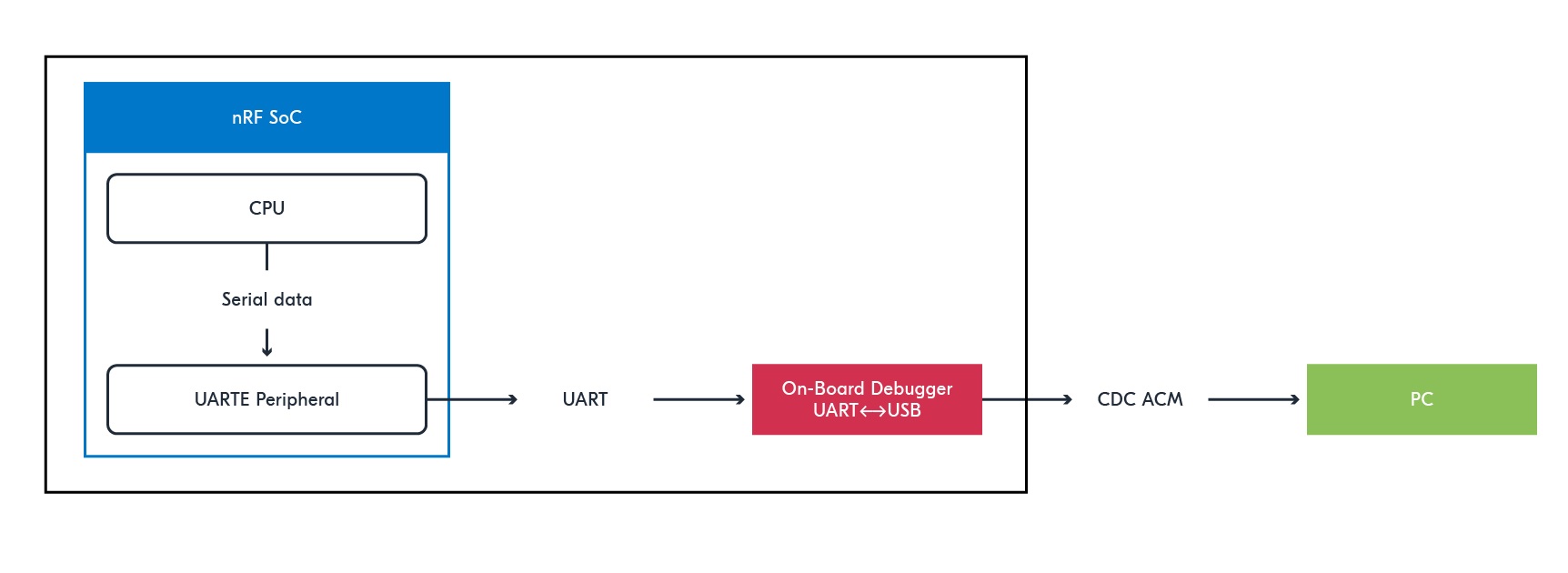
The application itself does not require any changes, but the bootloader application does. These changes are implemented using a different configuration file for the MCUboot application, as follows:
-
First copy the existing
prj_bootloader.conffile created in the previous step and rename itprj_serial_recovery.conf. Then, apply the following changes. -
Enable Serial Recovery over UART by adding:
prj_serial_recovery.conf# Enable Serial Recovery over UART CONFIG_MCUBOOT_SERIAL=y CONFIG_BOOT_SERIAL_UART=y -
Disable console UART, since Serial Recovery uses UART, by adding:
prj_serial_recovery.conf# Disable console UART, since Serial Recovery uses UART CONFIG_UART_CONSOLE=n -
Since with this configuration, the application is updated in place, only one slot is required to store the application. Configure the bootloader to use a single slot:
prj_serial_recovery.conf# Configure bootloader to use a single slot CONFIG_SINGLE_APPLICATION_SLOT=y -
Configure LED indication when Serial Recovery mode is active:
{workspace}/prj_serial_recovery.conf# Configure LED indication when Serial Recovery mode is active CONFIG_MCUBOOT_INDICATION_LED=y
You can then build the MCUboot application using
west build deps/bootloader/mcuboot/boot/zephyr --pristine --extra-conf ../../../../../prj_serial_recovery.conf -d build_bootloader
west flash -d build_bootloader,
it should start and execute as before. As the board is configured for the use of the MCUboot application in Serial
Recovery mode, it is ready for testing.
Upload a Firmware Update
We use a desktop tool called Auterm to send firmware updates via UART. Other tools can also be used, and alternative tools are presented here.
Read the instructions to download
and install the Auterm tool. Once ready, launch Auterm and follow the instructions below to update
your bike_computer program using Serial Recovery:
-
Reset the board while pressing Button1. It should restart but instead of jumping to the
bike_computerprogram, it should wait for an update to be receive. LED1 should turn on. -
Close any open UART connections to the board.
-
In Auterm, configure the COM port to use under the
Configtab and pressOpen. The connection should be established. -
In Auterm, select the
MCUmgrtab. UnderImages, selectGetand pressGo. You should see that the board is configured with one slot (Slot 0). -
Modify your
bike_computerprogram so that a difference in logging appears at application start. Modify the sign version to"1.0.1+0". Build the program without flashing it. -
In Auterm, select the
MCUmgrtab. UnderUpload, select thebuild/zephyr/zephyr.signed.binfile, check theReset after uploadbox and pressGoto start the upload. Upload should start and after it is finished, the board should reset and start again. -
In Auterm, select the
Terminaltab. You should see that your updated program has been successfully installed and started on the board. If you restart your board in bootloading mode, underImages, you should see that the image version has changed to1.0.1.
Intermediate Wrap-up
Before moving to the next section, make sure that you have accomplished the following:
- You have modified the MCUboot application configuration, built and flashed it. Upon reset, the board
launches the MCUboot application and successfully jumps to the
bike_computerprogram. - You have understood how the memory model of your board has been modified to use a MCUboot bootloader application.
- You have performed a firmware update download using Serial Recovery successfully and observed that
the updated
bike_computerprogram launches successfully.
Update the bike_computer Program over UART from the Application
In the previous section, we implemented a software update using Serial Recovery by utilising DFU over UART with the onboard UART-to-USB converter available on the development kit. However, incorporating a UART-to-USB converter into an embedded system is not usually practical, as this increases the bill of materials, power consumption, and complexity.
In this section, we implement a different mechanism that does not require an onboard UART-to-USB converter but rather makes uses of the USB MCU interface. This setup is illustrated in the diagram below:
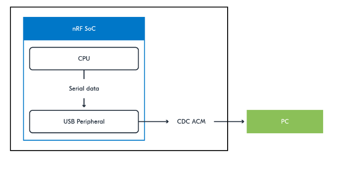
Using this mechanism with a SoC that comes with a built-in USB peripheral eliminates the need for additional hardware, thus reducing the cost and complexity of a system that uses wired DFU.
In order to implement this mechanism, you will first need to build and flash the MCUboot bootloader application by using
west build deps/bootloader/mcuboot/boot/zephyr --pristine --extra-conf ../../../../../prj_bootloader.conf -d build_bootloader
*** Booting MCUboot v2.4.0-rc1-3-gee39e2d694bd ***
*** Using Zephyr OS build v4.4.0 ***
I: Starting bootloader
I: Image index: 0, Swap type: none
I: Image index: 0, Swap type: none
I: Primary image: magic=unset, swap_type=0x1, copy_done=0x3, image_ok=0x3
I: Secondary image: magic=unset, swap_type=0x1, copy_done=0x3, image_ok=0x3
I: Boot source: none
I: Image index: 0, Swap type: none
I: Image index: 0, Swap type: none
I: Image index: 0, Swap type: none
I: Image index: 0, Swap type: none
I: Bootloader chainload address offset: 0x10000
I: Image version: v1.0.1
I: Jumping to the first image slot
Understand MCUboot Logging
It is important to understand the logging information provided by the MCUboot application in order to understand the update mechanism. The log contains the following information:
-
Information about images:
I: Primary image: magic=unset, swap_type=0x1, copy_done=0x3, image_ok=0x3 I: Secondary image: magic=unset, swap_type=0x1, copy_done=0x3, image_ok=0x3-
The possible values for
magicareBOOT_MAGIC_GOOD(1),BOOT_MAGIC_BAD(2) orBOOT_MAGIC_UNSET(3). -
The possible values for
swap_typeare
Value Symbol Description 1 BOOT_SWAP_TYPE_NONE Attempt to boot the contents of the primary slot. 2 BOOT_SWAP_TYPE_TEST Swap to the secondary slot.
Absent a confirm command, revert back on next boot.3 BOOT_SWAP_TYPE_PERM Swap to the secondary slot,
and permanently switch to booting its contents.4 BOOT_SWAP_TYPE_REVERT Swap back to alternate slot.
A confirm changes this state to NONE.5 BOOT_SWAP_TYPE_FAIL Swap failed because image to be run is not valid. 0xFF BOOT_SWAP_TYPE_PANIC Swapping encountered an unrecoverable error - The possible values for
copy_doneandimage_okareBOOT_FLAG_SET(1),BOOT_FLAG_BAD(2) orBOOT_FLAG_UNSET(3).
-
-
Information about the Boot source. It is set to none, unless the
magicof the primary slot isBOOT_MAGIC_GOOD, thecopy_doneof the primary slot isBOOT_FLAG_UNSETand the magic of the secondary slot is notBOOT_MAGIC_GOOD, in which case the Boot source is the primary slot. -
The other information can be deduced from the preceding ones.
After flashing the bike_computer program, the bootloader will simply attempt to jump to the application in
the primary slot.
The swap Algorithms used by MCUboot
MCUboot supports different ways of swapping firmware candidates:
-
Swap using scratch: The algorithm uses an additional scratch area to perform the swap. The main drawback of this method is that it makes extensive use of the scratch area, which can be problematic on non-volatile flash memory. This video explains the algorithm in detail.
-
Swap using move: The algorithm uses an additional sector in the primary slot to perform the swap. The use of segment is evenly distributed and this is particularly beneficial when there are a large number of segments. This video explains the algorithm in detail.
-
Swap using offset: This is essentially the same algorithm as Swap using move, but where the additional sector is allocated in the secondary slot.
Modify the bike_computer Program for Supporting DFU over UART
Implementing Serial Recovery did not require modifying the bike_computer program, because DFU was
implemented in the MCUboot bootloader application. In the new scenario, however, the DFU over UART is implemented
in the bike_computer program. The following changes are required:
- Modifiy the
prj_dfu.confconfiguration file with the following content:
prj_dfu.conf
# Changes required for MCUmgr
# Enable mcumgr DFU in application
CONFIG_MCUMGR=y
CONFIG_UART_MCUMGR=y

# Enable MCUMGR management for both OS and Images
CONFIG_MCUMGR_GRP_OS=y
CONFIG_MCUMGR_GRP_IMG=y

# Configure MCUMGR transport to UART
CONFIG_MCUMGR_TRANSPORT_UART=y
CONFIG_MCUMGR_TRANSPORT_LOG_LEVEL_INF=y

# Dependencies
# Configure dependencies for CONFIG_MCUMGR
# CONFIG_NET_BUF=y
CONFIG_ZCBOR=y

# Configure dependencies for CONFIG_MCUMGR_GRP_IMG
CONFIG_FLASH=y
CONFIG_IMG_MANAGER=y

# Configure dependencies for CONFIG_IMG_MANAGER
CONFIG_STREAM_FLASH=y
CONFIG_FLASH_MAP=y

# Configure dependencies for CONFIG_MCUMGR_TRANSPORT_UART
CONFIG_BASE64=y
CONFIG_CRC=y

# Enable USB subsystem
CONFIG_USB_DEVICE_STACK_NEXT=y
CONFIG_USBD_CDC_ACM_CLASS=y
CONFIG_CDC_ACM_SERIAL_INITIALIZE_AT_BOOT=y
CONFIG_USBD_CDC_ACM_LOG_LEVEL_OFF=y
CONFIG_UDC_NRF_THREAD_STACK_SIZE=2048
Read the comments in the configuration file to understand the requirements for supporting DFU over UART in the application.
- Note that the
nrf5340dk_nrf5340_cpuapp.overlayfile has already been modified to configure the COM port to be used for mcuMgr DFU:
nrf5340dk_nrf5340_cpuapp.overlay
/ {
...
  chosen {
    zephyr,uart-mcumgr = &cdc_acm_uart0;
  };
};
...
&zephyr_udc0 {
  cdc_acm_uart0: cdc_acm_uart0 {
    compatible = "zephyr,cdc-acm-uart";
  };
};
-
From the
prf_dfu.confconfiguration file, you can see that USB will be initialize at boot time (with theCONFIG_CDC_ACM_SERIAL_INITIALIZE_AT_BOOT0=yparameter). -
Build your
bike_computerprogram with the commandjust build bike_computer log_app+debug+gpio+display+sensor+phase_c yes prj_dfu.conf` -
Flash the updated program. You should see the same bootloader log in the serial terminal.
Upload a Firmware Update over UART
To upload a firmware update, first connect the “nRF USB” to your computer. This USB differs from the one connected to the
J-Link debugger and is located on the long side of your board. If you have updated the bike_computer program
as described in the previous section, another COM port should be available for connecting on your computer for connection
(e.g. /dev/ttyACM2 on Linux or COMX on Windows).
The steps for uploading a firmware update are as follows:
- In the Auterm window, configure the COM port to use under the
Configtab. Select the new COM port and establish the connection by clickingOpen. - In Auterm, select the
MCUmgrtab. UnderImages, selectGetand clickGo. You should see that the board is configured with two slots (“Slot 0” and “Slot 1”) - note that if you only flashed thebike_computerprogram usingwest flash, you may see only one slot. The first slot should be the one of the current application (e.g. version “1.0.1”). It should be active, confirmed and bootable. - Modify your
bike_computerprogram so that a difference in logging appears at start-up. Modify the patch number in theCONFIG_MCUBOOT_IMGTOOL_SIGN_VERSIONparameter. Build the program without flashing it. - In Auterm, select the
MCUmgrtab. UnderUpload, select thebuild/zephyr/zephyr.signed.binfile, check theReset after uploadbox and clickGoto start the upload. Upload should start and after it is finished, the board should reset and start again. - In a serial terminal, you should see the following:
Serial terminal
*** Booting MCUboot v2.4.0-rc1-3-gee39e2d694bd *** *** Using Zephyr OS build v4.4.0 *** I: Starting bootloader I: Image index: 0, Swap type: test I: Primary image: magic=unset, swap_type=0x1, copy_done=0x3, image_ok=0x3 I: Secondary image: magic=good, swap_type=0x2, copy_done=0x3, image_ok=0x3 I: Boot source: none I: Image index: 0, Swap type: test I: Image index: 0, Swap type: test I: Image index: 0, Swap type: test I: Starting swap using offset algorithm. I: Image index: 0, Swap type: none I: Image index: 0, Swap type: revert I: Bootloader chainload address offset: 0x10000 I: Image version: v1.0.2 -
As you can see in the log, the second slot is recognized as valid and the bootloader will start a swap to the secondary slot. After the move algorithm has been applied, the bootloader jumps to the first slot and you should see that your updated
bike_computerprogram (with the updated image version) starts correctly. -
If you update the images in Auterm by clicking
Goin theImagestab, you should see two slots with the latest image (e.g. version “1.0.2”) in slot 0 and the oldest image (e.g. version “1.0.1”) in slot 1. The two images have been swapped. At this point, the latest version in slot 0 has not been confirmed. -
If you reset your board (without confirming the update), your should see the following log:
Serial terminalThe update has not been confirmed, so the oldest image is restored by swapping. Your oldest*** Booting MCUboot v2.4.0-rc1-3-gee39e2d694bd *** *** Using Zephyr OS build v4.4.0 *** I: Starting bootloader I: Image index: 0, Swap type: revert I: Primary image: magic=good, swap_type=0x2, copy_done=0x1, image_ok=0x3 I: Secondary image: magic=unset, swap_type=0x1, copy_done=0x3, image_ok=0x3 I: Boot source: none I: Image index: 0, Swap type: revert I: Image index: 0, Swap type: revert I: Image index: 0, Swap type: revert I: Starting swap using offset algorithm. I: Secondary image: magic=unset, swap_type=0x1, copy_done=0x3, image_ok=0x3bike_computerprogram should start and you can confirm with Auterm that the slots have been reverted, with the oldest image now in slot 0. -
If you boot again, no swap takes place and the oldest image runs.
- It is time to confirm the newest image that is stored in slot 1. You can do this by selecting slot 1 in the
MCUmgrtab, by choosingSet, checking theConfirmbox and clickingGo. Slot 1 should now appear as permanent, bootable and pending. - If you reset the board again, you should see the following log:
Serial terminalThe secondary image is swapped again and your newest
*** Booting MCUboot v2.4.0-rc1-3-gee39e2d694bd *** *** Using Zephyr OS build v4.4.0 *** I: Starting bootloader I: Image index: 0, Swap type: perm I: Primary image: magic=good, swap_type=0x4, copy_done=0x1, image_ok=0x1 I: Secondary image: magic=good, swap_type=0x3, copy_done=0x3, image_ok=0x1 I: Boot source: none I: Image index: 0, Swap type: perm I: Image index: 0, Swap type: perm I: Image index: 0, Swap type: perm I: Starting swap using offset algorithm. I: Image index: 0, Swap type: none I: Image index: 0, Swap type: none I: Image index: 0, Swap type: none I: Bootloader chainload address offset: 0x10000 I: Image version: v1.0.2 I: Jumping to the first image slotbike_computerprogram starts. - If you update the images in Auterm by clicking
Goin theImagestab, slot 0 should now contain the newest image as active, confirmed and bootable. - You can give it one more try with a newest version of the
bike_computerprogram (e.g. version “1.0.3”). It should upload to slot 1 and you could confirm it after the initial swap so that it is not reverted.
Final Wrap-up
To achieve a fully functional bootloading process and understand its key principles, make sure you have completed the following:
- You understand how the device’s flash is partitioned.
- You have successfully tested the Serial Recovery process.
- You have successfully tested DFU over UART for the
bike_computerprogram. - You understand how the MCUboot bootloader application analyses image slots at startup and performs an image swap if applicable.
- You have confirmed a firmware update after a test swap.